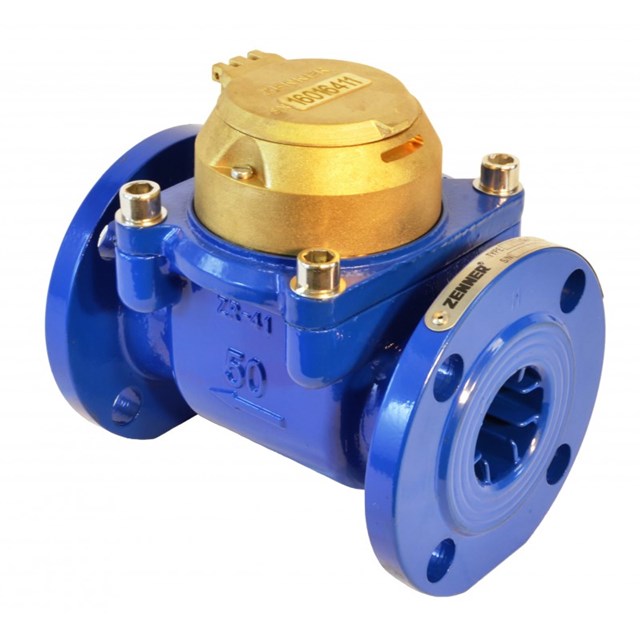
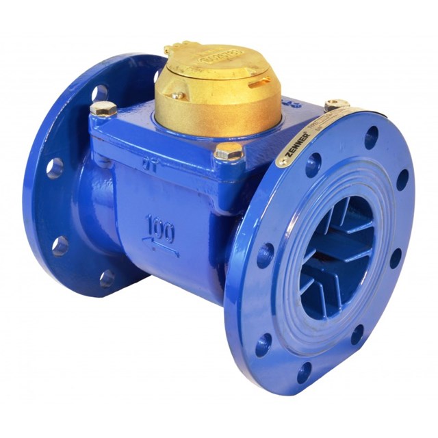
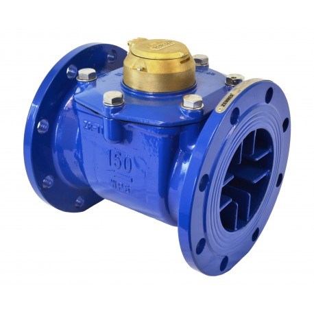
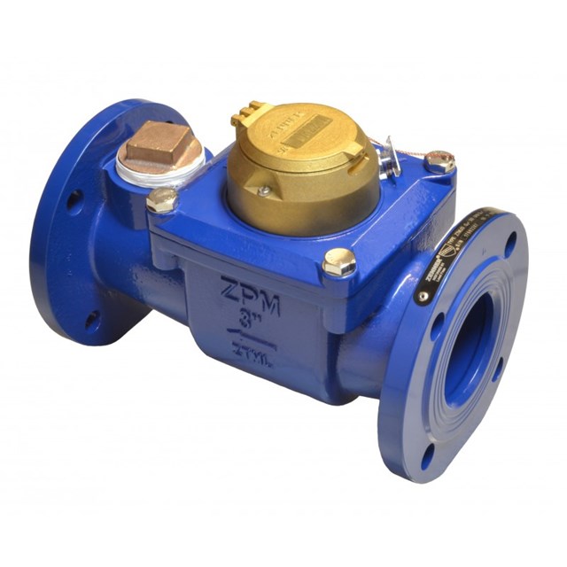
Zenner ZTM - Cast Iron Turbine Water Meter
ZENNER Cast Iron Turbine Meters are designed for applications where flows are usually moderate to high and occasionally low.
OPERATION: Water flows through the turbine section which causes the rotor to turn proportionately to the quantity of water flowing through the meter. A drive magnet transmits the motion of the rotor to a driven magnet located within the hermetically sealed register. The magnet is connected to a gear train which translates the rotations into volume totalization displayed on the register dial face. The only moving parts in the meter are the rotor assembly and vertical shaft.
CONSTRUCTION: ZENNER Cast Iron Turbine Meters consist of four basic components: The main housing, cover plate, measuring element, and sealed register. The main housing and cover plate are made of epoxy coated ductile cast iron. The measuring element assembly includes the rotor assembly, vertical shaft and a calibration vane which eliminates the need for calibration change gears.
MAINTENANCE: ZENNER Cast Iron Turbine Meters are engineered and manufactured to provide long-term service and operate virtually maintenance free. If necessary the universal measuring element (UME) can be removed from the main case for maintenance. Interchangeability of certain parts between like sized meters minimizes spare parts inventory.
CONFORMANCE: ZENNER Cast Iron Turbine Meters are tested and comply with AWWA C701 Class II performance standards. These Meters comply with the lead-free provisions of the Safe Drinking Water Act and are certified to NSF/ANSI Standards 61 and 372.
STRAINERS: ZENNER recommends the use of a separate strainer upstream from the turbine meter. Strainers reduce the chance of damage to the rotor as well as the frequency in which it must be removed for inspection. The lack of a strainer may void the warranty of the turbine meter.
CONNECTIONS: Companion flanges for installation of meters on various pipe types and sizes are available in bronze or cast iron.


| MODEL | ZTM02 | ZTM03 | ZTM04 | ZTM06 | ZTM08 | ZTM10 | ZTM12 | |
| SIZE | 2" | 3" | 4" | 6" | 8" | 10" | 12" | |
| Flow rate maximum intermittent | USGPM | 400 | 550 | 1250 | 2500 | 4500 | 7000 | 8800 |
| Maximum continuous | USGPM | 200 | 450 | 1000 | 2000 | 3500 | 5500 | 6200 |
| Optimum operating flow range | USGPM | 3-200 | 5-550 | 10-1250 | 20-2500 | 30-4500 | 50-7000 | 90-8800 |
| Low flow rate | USGPM | 2 | 2-1/12 | 5 | 12 | 20 | 45 | 65 |
| Start-up flow rate | USGPM | 7/8 | 1-1/8 | 1-3/8 | 7-1/2 | 8 | 15 | 15 |
| Maximum Working Pressure | P.S.I. | 150 | 150 | 150 | 150 | 150 | 150 | 150 |
| Maximum Temperature | Deg. F | 150 | 150 | 150 | 150 | 150 | 150 | 150 |
| Length | Inches | 7-7/8 | 8-7/8 | 9-7/8 | 11-7/8 | 13-3/4 | 17-3/4 | 19-5/8 |
| Height | Inches | 8 | 9 | 10 | 12 | 14 | 15-3/4 | 18-3/4 |
| Width | Inches | 6 | 7-1/2 | 9 | 11 | 13-1/2 | 16 | 19 |
| Weight | Pounds | 24 | 32 | 38 | 84 | 126 | 225 | 255 |
| Number of holes per flange | 4 | 4 | 8 | 8 | 8 | 12 | 12 | |
CAST IRON Turbine Water Meters are used in measurement of potable cold water in commercial and industrial services where flows are in one direction.
Sizes 2” through 12”
Zenner ZTM - Cast Iron Turbine Water Meter Applications
- Water Meter Applications
Zenner ZTM - Cast Iron Turbine Water Meter Resources and Product Information
Our Brands
